VNA Calibration Standard
Fixed Load Series
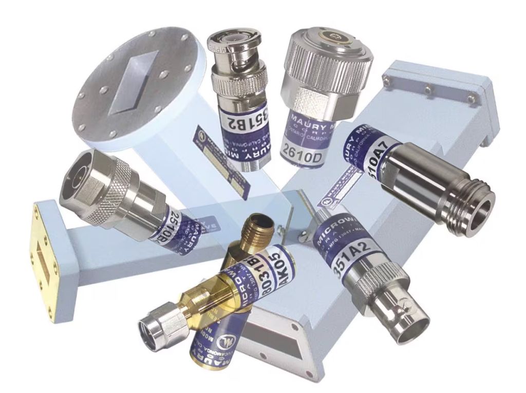
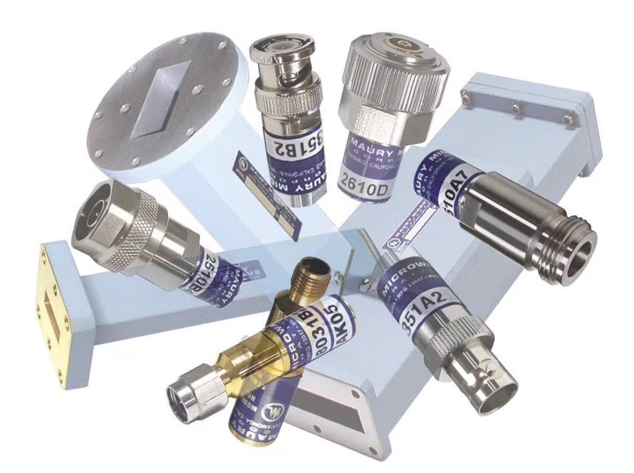
A precision fixed termination (or load) consists of an immovable, (fixed) termination which, when mated to the end of a trans-mission line or cable, absorbs nearly all of the signal energy traveling toward it. An ideal “matched” condition exists when a termination with an impedance value of Z0, is connected to the end of a transmission line or cable that also has a characteristic impedance of Z0. Such an ideal “matched” condition (one with no mismatch between the termination and its mated line or cable) is critical if a voltage standing wave ratio (VSWR) of 1.0:1 is to be achieved in a system with a 50 or 75 ohm impedance value. Simply put, the more closely the 1.0:1 ratio is approached, the more accurate the measurements that can be made from a system.
Key Features
Models
Specifications
Frequency Range (Coaxial)
Frequency Range (Waveguide)
VSWR
DC to 67 GHz
2.6 to 50 GHz
1.02:1 to 1.2:1
Features & Benefits
- Calibration-grade metrology standards
- Used for VNA calibration and/or calibration validation
Filters
| Name | Connector 1 | Frequency Range (GHz) | Gender 1 | VSWR (max) |
|---|---|---|---|---|
| 2510E2 | Type N | DC-18 | Female | 2-4 GHz, 1.04, 4-18 GHz, 1.065, DC-2 GHz, 1.025 |
| 2510F2 | Type N | DC-18 | Male | 2-4 GHz, 1.04, 4-18 GHz, 1.065, DC-2 GHz, 1.025 |
| 2610F1 | 7mm | DC-18 | Female | 2-8 GHz, 1.03, 8-18 GHz, 1.06, DC-2 GHz, 1.02 |
| 2931A | TNC | DC-18 | Female | 12.0 to 18.0 GHz, ≤ 1.10, 4.0 to 12.0 GHz, ≤ 1.08, DC to 4.0 GHz, ≤ 1.04 |
| 2931B | TNC | DC-18 | Male | 12.0 to 18.0 GHz, ≤ 1.10, 4.0 to 12.0 GHz, ≤ 1.08, DC to 4.0 GHz, ≤ 1.04 |
| 351A2 | BNC | DC-10 | Female | 2-4 GHz, 1.1, 4-10 GHz, 1.2, DC-2 GHz, 1.04 |
| 351B2 | BNC | DC-10 | Male | 2-4 GHz, 1.1, 4-10 GHz, 1.2, DC-2 GHz, 1.04 |
| 7831A1 | 1.85mm | DC-67 | Female | 1-10 GHz, 1.07, 10-26.5 GHz, 1.1, 26.5-67GHz , 1.2, DC-1 GHz, 1.02 |
| 7831B1 | 1.85mm | DC-67 | Male | 1-10 GHz, 1.07, 10-26.5 GHz, 1.1, 26.5-67GHz , 1.2, DC-1 GHz, 1.02 |
| 7931A2 | 2.4mm | DC-50 | Female | 4-50 GHz, 1.16, DC-4 GHz, 1.02 |
| 7931B2 | 2.4mm | DC-50 | Male | 4-50 GHz, 1.16, DC-4 GHz, 1.02 |
| 8031A6 | 3.5mm | DC-26.5 | Female | DC-2 GHz, 1.025, 18-26.5 GHz, 1.085, 2-18 GHz, 1.045 |
| 8031B6 | 3.5mm | DC-26.5 | Male | DC-2 GHz, 1.025, 18-26.5 GHz, 1.085, 2-18 GHz, 1.045 |
| 8583A1 | BNC 75Ω | DC-12 | Female | 2-4 GHz, 1.04, 4-12 GHz, 1.1, DC-2 GHz, 1.02 |
| 8583B1 | BNC 75Ω | DC-12 | Male | 2-4 GHz, 1.04, 4-12 GHz, 1.1, DC-2 GHz, 1.02 |
| 8775A4 | 2.92mm | DC-40 | Female | 4-40 GHz, 1.12, DC-4 GHz, 1.02 |
| 8775B4 | 2.92mm | DC-40 | Male | 4-40 GHz, 1.12, DC-4 GHz, 1.02 |
| C301 | WR137 | 5.85-8.2 | Female | 1.02 |
| E301F | WR229 | 3.3-4.9 | Female | 1.02 |
| F301C | WR159 | 4.9-7.05 | Female | 1.02 |
| G301 | WR187 | 3.95-5.85 | Female | 1.02 |
| H301A | WR112 | 7.05-10 | Female | 1.015 |
| J301A | WR22 | 33-50 | Female | 1.04 |
| K301 | WR42 | 18-26.5 | Female | 1.025 |
| M301A | WR75 | 10-15 | Female | 1.02 |
| N301 | WR51 | 15-22 | Female | 1.025 |
| P301A | WR62 | 12.4-18 | Female | 1.02 |
| Q301A | WR34 | 22-33 | Female | 1.025 |
| S301A | WR284 | 2.6-3.95 | Female | 1.025 |
| U301 | WR28 | 26.5-40 | Female | 1.025 |
| X301A | WR90 | 8.2-12.4 | Female | 1.15 |
No products match your current filters.
Discover more
Related Products
Explore More
Related Resources
01
Characterizing Uncertainty in S-Parameter Measurements
As technologies evolve and requirements become more challenging, implementing processes that increase confidence in measurements and ensure accurate and reliable characterization—and product performance—are critical. Learn how to characterize uncertainty with S-parameter measurements in this application note.