Electromagnetic compatibility (EMC) immunity testing is used to assess a device’s resistance to external electromagnetic influences, analyzing whether it continues to operate as intended or experiences malfunctions or other operational issues.
EMC testing traditionally evaluated devices operating below 18 GHz, but this is no longer the case in today’s environment. With 5G FR2, automotive radar, and mmWave technologies, there are a myriad of components and systems operating at much higher frequencies beyond 18 GHz.
While international EMC standards such as IEC61000 continue evolving to address higher-frequency technologies, military standards have already established high-frequency EMC immunity test requirements. MIL-STD-461 RS103, for example, defines radiated susceptibility testing up to 18 GHz, with optional extensions to 40 GHz.
Key Challenges of High-Frequency EMC Immunity Testing
As EMC immunity testing moves into higher frequencies, engineers must overcome several challenges to generate accurate, repeatable electromagnetic fields:
- Increased RF losses: Higher frequencies experience greater losses through conductive cables and free space, reducing the RF power available at the antenna.
- Field strength requirements: Although there are higher RF losses as frequency increases, required electric field strength must still be achieved.
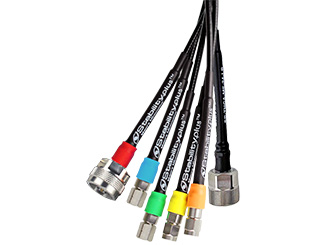
- Measurement stability: At higher frequencies, there is increased sensitivity to mechanical variation. Cables often move during EMC testing, and even small movements can impact amplitude and phase stability. Incorporating stable components minimizes drift and maintains calibration over time.
- Broadband test coverage: Broadband solutions cover wide frequency ranges and can, for example, support field strengths from 10 V/m to 200 V/m without requiring frequent changes to test bench components, reducing setup complexity and measurement time.
Example MIL-STD-461 Test Setup: 200 V/m at 40 GHz
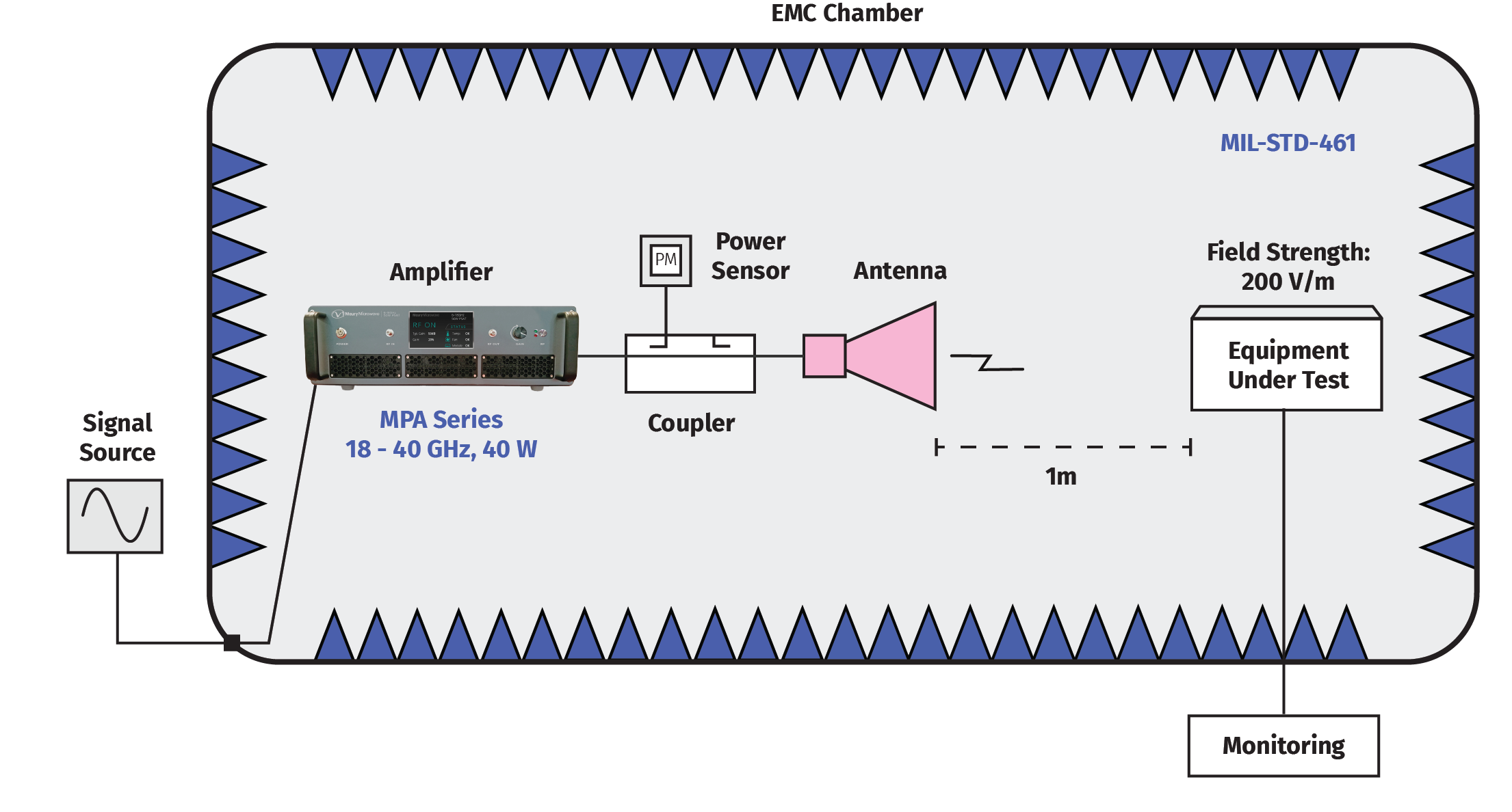
The example below illustrates a MIL-STD-461 RS103 radiated susceptibility test requiring a 200 V/m electric field at 40 GHz with the equipment under test (EUT) positioned 1 meter from the antenna.
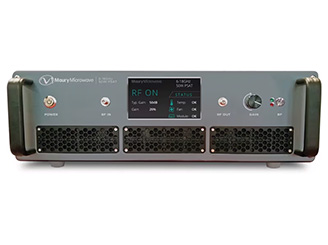
In the setup, the power amplifier is located inside the EMC chamber to minimize the RF cable length between the amplifier and antenna. Using this configuration with a proper a high-gain horn antenna (gain: 20 dBA), a 40 W Maury Microwave MPA-series amplifier supports the required field strength.
Alternatively, the amplifier can be positioned outside the EMC chamber. However, the longer RF cable introduces additional insertion loss between the amplifier and antenna. After accounting for cable loss and antenna mismatch, the required amplifier output can increase to approximately 80–100 W to achieve the same field strength.
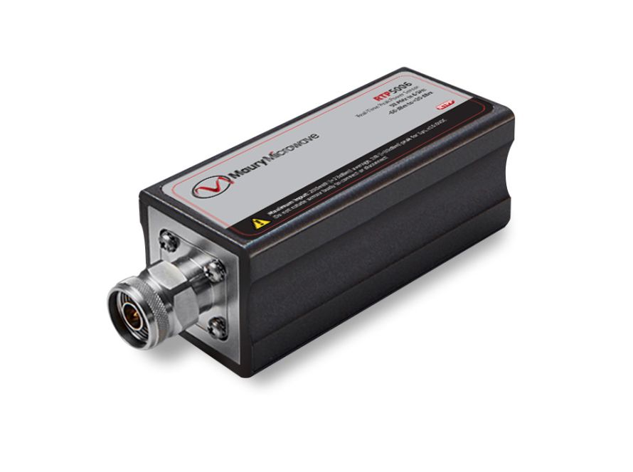
The interactive diagram below follows the RF signal chain used to generate, measure, and verify the required 200 V/m electric field.