What Is Pulse Compression Radar and What’s Needed to Test It?
July 21, 2025
From surveillance operations to mission-critical defense systems, pulsed radar is central to various applications requiring precise target information, such as range and velocity. In this blog, we’ll explore how pulsed radar works and how engineers can attain high signal fidelity to ensure their systems meet performance requirements.
Pulsed Radar
Traditional pulsed radar systems transmit high-power RF pulses.
The width of the pulse (or the length of time that the pulse is “on”) affects radar resolution, or how well it can distinguish between different targets. If the pulse is too wide, the resolution will be poor; two adjacent targets may appear as one large signature, while finer resolution will be able to resolve these closely spaced targets as two separate entities.
Although shorter pulses have better resolution, they carry less energy and thus limit long-range performance.
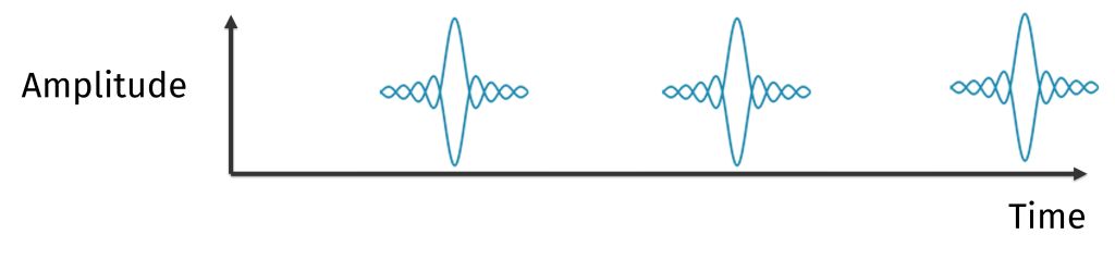
Transmit pulse amplitude and frequency characteristics.
Pulse compression can cause several challenges, such as unwanted peaks adjacent to the main return signal, referred to as sidelobes. Weaker target signals can easily become hidden in the sidelobes of a stronger return. If the transmitted signal is distorted by ringing and other artifacts, sidelobes can increase in magnitude. Engineers can apply amplitude weighting to soften the edges of the pulse and reduce sidelobe levels.
Compressed receive pulse showing time sidelobes.
The Building Blocks of a Pulsed Radar System
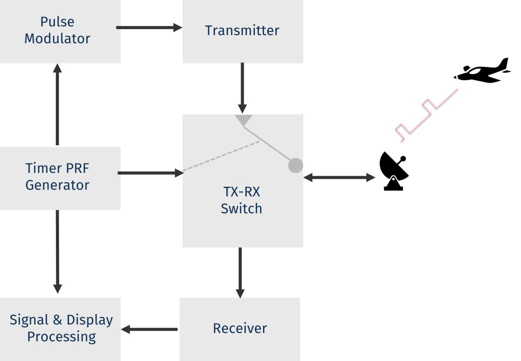
As shown in the simplified radar block diagram, a PRF generator creates a steady timing signal that defines and controls the pulse repetition frequency, determining the number of pulses transmitted per second. The pulsed RF signal is then sent to the pulse modulator, which gates the on-off intervals and controls key pulse characteristics, such as the envelope, pulse width, and shape. After passing through the transmitter, which amplifies the transmission to the required power levels, the signal is routed via the TX-RX switch to the antenna to radiate the pulse toward the target.
Simplified radar system block diagram.
A portion of the returned energy is intercepted by the target and re-radiated in multiple directions. Of this re-radiated energy, the portion that returns to the radar is collected by the antenna and directed to the receiver via the TX-RX switch. After processing, the system is able to extract valuable target data.
Ensuring High-integrity Radar Signals
Engineers want to ensure that their pulsed radar systems perform as intended and that starts with transmitting clean, properly shaped pulses. Distortions such as overshoot, ringing, and droop put that critical objective at risk. In addition to sidelobe magnitude, artifacts interfere with the matched filtering process used in CHIRP radar to compress the return signal. This can degrade the pulse compression profile and obscure the true target signal.
Optimal performance relies on high-performance measurement test setups, comprised of amplifiers, couplers, and peak power sensors.
The MPA series driver amplifier produces clean, consistent pulses with low distortion and high linearity, ensuring the required signal power is delivered to the device under test.
The LLC series high-power, low-loss bidirectional coupler samples the input signal without causing disruptions. A waveguide coupler would be required on the high power output of the transmitter or solid state amplifier. The RTP5000 series real-time peak power sensors provide 100,000 measurements per second, rise time under 3 nanoseconds, wide video bandwidth of 195 MHz, and fine 100 picoseconds time resolution to capture the real-time performance and signal artifacts of radar pulses.
Set up for measuring pulse performance of a radar high-power solid-state amplifier.
In pulsed radar systems, analyzing real-world pulse behavior is key to achieving advanced, reliable performance. Maury amplifiers, couplers, and power sensor solutions provide the capabilities needed to measure, characterize, and put the confidence within every radar pulse that’s transmitted and received.